Communication and sharing promote growth
Joining Hands for Development!

1- Battery tray / energy storage pack box aluminum alloy welding process characteristics
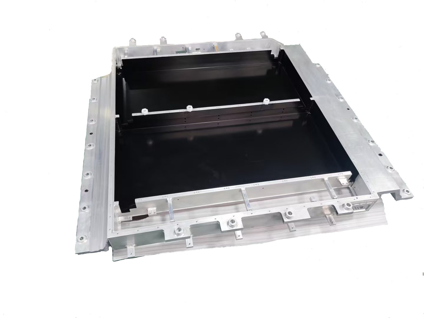
In the manufacturing of new energy liquid-cooled Pack boxes, battery trays and other products, liquid cooling channels and multi-cavity structures are typical complex design features (as shown in Figure 1). Such structures often include the following features:

Figure 1: Typical design of a battery tray
Three-dimensional space interlacing: the flow channels are distributed in a serpentine shape, with a large number of spatial turning points;
Multi-level connection: the main cavity and sub-cavity are connected by thin-walled partitions (thickness 2-3mm);
Miniaturization features: small flow channel cross-section size (the minimum wall thickness of the aluminum profile flow channel is 1.2mm) and poor welding accessibility.
2- Difficulty analysis of combining multiple welding technologies in battery tray manufacturing
In the practice of battery tray manufacturing, it is necessary to combine multiple welding technologies, such as the coordinated application of friction stir welding (FSW), cold metal transition welding (CMT), traditional melting welding (TIG/MIG) and other technologies. This combination aims to take into account lightweight, strength, sealing and production efficiency, but it also faces the following core difficulties:
a. The problem of coordinated heat input of multiple processes
Different welding technologies (such as FSW and laser welding) have large differences in heat input, which can easily cause material performance mutations and thermal deformation, and need to be solved by optimizing the welding sequence and parameter adjustment.
b. Equipment compatibility and efficiency bottleneck
Equipment switching is complex and parameter synchronization accuracy requirements are high. Modular workstation design and intelligent welding machines are required to improve collaborative efficiency and reduce cycle time.
c. Challenges of balancing sealing strength and cost
The risk of leakage at the intersection of multiple welds is high (accounting for 70% of defects), and redundant sealing + topology optimization design is required.

3-Engineering practice: Battery tray, energy storage liquid cooling PACK box multi-welding process coordination
a. Weld scar position planning
· Welding position optimization: In the product design stage, the rationality of the welding position should be fully considered to avoid weld scars appearing in key parts or areas that affect product functions. For example, adjust the gap between the front frame and the water nozzle to prevent weld scar interference; optimize the welding position of the water nozzle to reduce the impact on product performance.
· Matching with product structure: The welding position should match the product structure to ensure that the weld can withstand various loads and stresses during the use of the product. For example, in the liquid cooling plate project, the structural stability and reliability of the product are improved by rationally planning the welding position.
· Easy to operate and detect: The welding position should be convenient for operators to perform welding operations and subsequent quality inspections. For example, avoid welding in locations that are difficult to reach or have poor visibility to improve welding efficiency and quality.
b. Weld scar control
· Weld scar size: The size of the weld scar needs to be strictly controlled. Generally, the weld scar height is required to be within the range of 4/6mm, and the weld scar does not exceed the plane to ensure the appearance and assembly accuracy of the product. For example, in the liquid cooling plate project, the size of the weld scar was successfully controlled by adjusting the welding parameters and process, avoiding the impact of the weld scar on product performance and quality.
· Weld scar shape: The weld scar shape should be as regular as possible to avoid excessive melting or incomplete fusion. By optimizing welding parameters and operating techniques, the weld scar shape can be effectively improved and the weld quality can be improved.
· Grinding treatment: For the concave weld marks produced at the friction welding position, grinding treatment is used to ensure a smooth surface to meet the product appearance and performance requirements.
c. Welding sequence optimization
· Partition welding: For large products, the method of partition welding can effectively control the overall deformation. By dividing the product into several areas and welding them in sequence, the heat concentration during the welding process can be reduced and the risk of thermal deformation can be reduced.
· Step-by-step correction: During the welding process, the step-by-step correction method is used to adjust the welding deformation in time. By continuously measuring and correcting the deformation of the product during the welding process, the dimensional accuracy and shape of the final product are ensured to meet the design requirements.
· Optimize the welding path: Rationally plan the welding path to avoid repeated welding in the same area and reduce heat input. For example, in the liquid cooling plate project, the heat input during the welding process was reduced and the welding quality was improved by optimizing the welding path.
d. Deformation collaborative control
The liquid cooling plate undergoes thermal deformation during the welding process, resulting in a decrease in the dimensional accuracy of the product.
Optimization measures:
· Use partition welding and step-by-step correction methods to control the overall deformation.
· Optimize welding parameters, reduce current and voltage, and reduce heat input.
· Use fixtures to fix the product to reduce movement and deformation during welding.
Use symmetrical welding method to make welding heat evenly distributed.
We will regularly update you on technologies and information related to thermal design and lightweighting, sharing them for your reference. Thank you for your attention to Walmate.