
Communication and sharing promote growth
Joining Hands for Development!

The battery pack is the core energy source of new energy vehicles, providing driving power for the entire vehicle. We generally evaluate the advantages and disadvantages of battery pack technology from the dimensions of efficiency (energy density), safety, manufacturing and maintenance costs.
In battery design, the voltage of a single cell is only about 3-4V, while the voltage required by electric vehicles is at least 100V. New cars now even have a voltage of 700V/800V, and the output power is generally 200W, so the battery needs to be boosted. In order to meet the current and voltage requirements of electric vehicles, different cells need to be connected in series or parallel.
The battery pack is composed of battery cells, electronic and electrical systems, thermal management systems, etc., which are enclosed by a battery frame structure - base plate (tray), frame (metal frame), upper cover plate, bolts, etc. How to "package" these components and systems into a whole more efficiently and safely has always been a topic of continuous research and exploration for the entire industry.
Previous article: Innovation and development of battery integration technology
The origin of power battery group technology can be traced back to the 1950s, and originated in the former Soviet Union and some European countries. This technology was originally used as an engineering and manufacturing concept to determine the physical similarities of parts (universal process routes) and establish their efficient production.
The core of Group Technology (GT) is to identify and explore the similarities of related things in production activities, classify similar problems into groups, and seek relatively unified optimal solutions to solve this group of problems to achieve economic benefits. In the field of power batteries, group technology mainly involves the technology of integrating batteries from single cells into battery packs (Packs), including structure, thermal management, electrical connection design and battery management system (BMS) technology.
The earlier grouping technology in the automotive field is MTP (Module To Pack), which means that the cells are first integrated into modules, and then the modules are integrated into Packs. This technology is characterized by detachable and replaceable modules, which have good maintainability, but the grouping efficiency is low. With the development of technology, the grouping technology has undergone a transformation from MTP to CTP (Cell To Pack). CTP technology refers to the technology of directly integrating cells into Packs, eliminating the traditional module structure and improving grouping efficiency and production efficiency. In recent years, the industry is also exploring grouping technologies such as CTC (Cell To Chassis), CTB (Cell To Body & Bracket) and MTB (Module To Body) with higher integration efficiency.
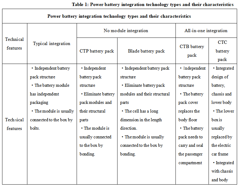
In the field of power batteries and electrochemical energy storage, the main technological advances of lithium batteries come from structural innovation and material innovation. The former is to optimize the structure of "cell-module-battery pack" at the physical level to achieve the goal of both improving the volume energy density of the battery pack and reducing costs; the latter is to explore battery materials at the chemical level to achieve the goal of both improving the performance of single cells and reducing costs. This article focuses on the impact of different structural integration technologies on battery pack manufacturing technology and the direction of innovative development from the perspective of battery pack structural integration. The current key technologies for power battery integration are shown in the figure below:
1-MTP has been eliminated
At the beginning of the current wave of electric vehicle development, many oil-to-electric new energy vehicle models have been launched. They continue the spatial layout and styling design of traditional gasoline vehicles. Engineers have assembled a relatively large battery cell module by connecting a certain number of individual battery cells in series/parallel, and then placed several such battery cell modules into the battery pack, which is the familiar "MTP" battery pack. Since the battery pack needs to be "packaged" more than twice, the number of required components is extremely large, and the battery pack appears as "three layers inside and three layers outside", with too many redundant parts occupying more system volume and weight, resulting in poor volumetric energy density and gravimetric energy density of the "MTP" battery pack. Additionally, since the design of gasoline vehicles did not specifically reserve space for the battery, the battery system can only be "squeezed in wherever it fits", leading to poor product competitiveness and user experience.
Since the launch of new intelligent electric vehicle platforms represented by Tesla, native pure electric vehicles have enabled battery packs to be installed in ideal spatial locations in a more efficient and regular manner, the three-electric systems can be more reasonably laid out, and the vehicle's electronic and electrical architecture and thermal management design can be more efficiently integrated. The vehicle's product strength in terms of energy efficiency, endurance, and intelligence has been greatly enhanced.
2-Integrated Technology 2.0 Era——CTP
The MTP structure battery pack has a significant space utilization problem. The space utilization of the battery cell to the module is 80%, the space utilization of the module to the battery pack is 50%, and the overall space utilization is only 40%. The module hardware cost accounts for about 14% of the total battery cost. This low space utilization structure cannot meet the development requirements of new energy vehicles. Under the framework of the battery cell → module → battery pack → body integration idea, if the vehicle wants to load as much power as possible in the limited chassis space and improve the volume utilization, it is necessary to consider the standardization of each integration step. As the market demand for driving range continues to rise, the volume of a single battery module continues to increase, which indirectly leads to the emergence of the CTP solution.
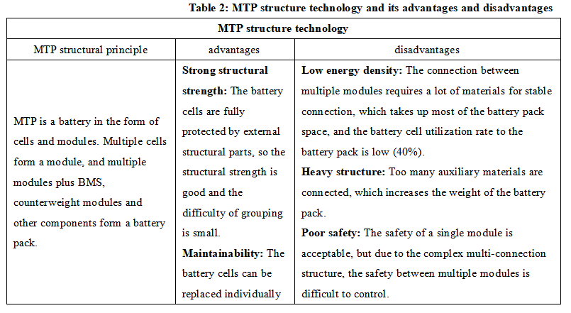
CTP structure technology was born for the consideration of safety, packaging complexity, cost reduction, etc. Under the premise of ensuring the safety of the battery cell, CTP technology reduces the internal cables and structural parts. Compared with MTP technology, CTP technology has no module structure and directly packages the battery cell into a battery pack before installing it on the vehicle.
There are currently two main ideas. One is to regard the Pack as a complete large module that replaces the structure of multiple small modules inside, represented by CATL; the other is to consider using a module-free solution during design, and design the battery itself as the strength participant, such as BYD's blade battery.
The core point of CTP technology is to cancel the module design. The battery cell is directly combined with the shell, reducing the use of end plates and partitions. The problems that follow are the fixation of the battery pack and thermal management.
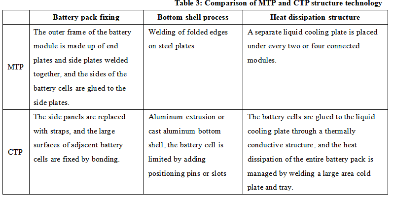
In fact, the original product of the CTP battery pack was not a pure module-free design, but a design that merged the original small modules into three large modules and two medium modules, and there were also aluminum end plates at both ends, so in theory it is still MTP, but there are indeed great improvements in structure.
After the introduction of CTP 3.0, CATL presented a more advanced manufacturing method, achieving a completely module-free design. The battery cells have been changed from a vertical orientation along the height to a horizontal position. Additionally, a new cooling solution has been implemented between the battery cells, which not only dissipates heat but also provides support, cushioning, insulation, and temperature control functions. The bottom shell has also been designed with a limiting fixation feature.
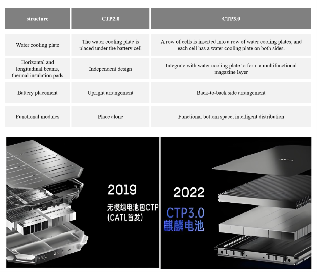
Figure 1: Comparison between CATL Kirin Battery CTP2.0 and CTP3.0
3-Integrated Technology 3.0 Era——CTB, CTC
a.CTB technology
CTP technology is a major step forward in battery structure innovation, but it has not made a breakthrough in the battery pack itself. In CTP technology, the battery pack is still an independent component. Compared with CTP's streamlined strategy for battery packs, CTB technology combines the body floor panel and the battery pack cover into one. The flat sealing surface formed by the battery cover, the door sill, and the front and rear beams seals the passenger compartment with sealant, and the bottom is assembled with the body through the installation point. When designing and manufacturing the battery pack, the battery system is integrated with the body as a whole, the sealing and waterproof requirements of the battery itself can be met, and the sealing of the battery and the passenger compartment is relatively simple, and the risks are controllable.
In this way, the original sandwich structure of "battery pack cover-battery cell-tray" is transformed into a sandwich structure of "body underbody integrated battery pack cover-battery cell-tray", reducing the space loss caused by the connection between the body and the battery cover. In this structural mode, the battery pack is not only an energy source, but also participates in the force and transmission of the whole vehicle as a structure.
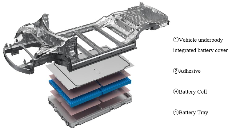
Figure 2: Schematic diagram of CTB technology structure
b.CTC technology
After adopting the CTC method, the battery pack is no longer an independent assembly, but is integrated into the body of the vehicle, which optimizes the product design and production process, reduces the number of vehicle parts, especially reduces the internal structural parts and connectors of the battery, has the inherent advantage of lightweight, maximizes the space utilization, and provides space for increasing the number of batteries and improving the driving range. Under the condition that the electrochemical system itself remains unchanged, the driving range can be increased by increasing the number of batteries.
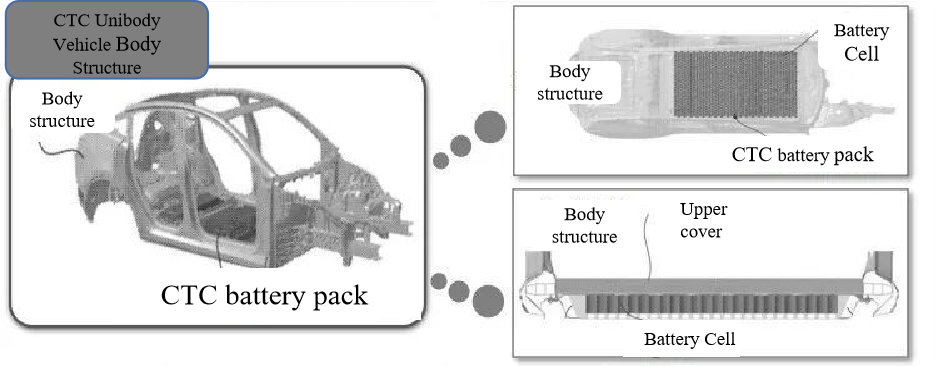
Figure 3: Tesla CTC technology structure diagram
For example, Tesla and other automakers have successively launched CTC technology models. At the cell level, they can use multifunctional elastic sandwich structures and large-area water cooling technology, and superimpose the anti-collision space reuse technology at the bottom of the battery pack brought by integrated development, taking into account the grouping efficiency, heat dissipation and safety, and promoting the application of CTC technology from the two dimensions of cell optimization and vehicle structure protection. At the level of vehicle integrated development, the battery cell is directly integrated into the chassis, eliminating the links of modules and battery packs. The integration of the three major electric systems (motor, electronic control, battery), the three minor electric systems (DC/DC, OBC, PDU), the chassis system (transmission system, driving system, steering system, braking system) and autonomous driving related modules is realized, and the power distribution is optimized and energy consumption is reduced through the intelligent power domain controller.
4-Changes in specific requirements for battery boxes for CTP, CTB and CTC technologies
In the traditional battery pack structure, the battery module plays the role of supporting, fixing and protecting the battery cell, while the battery box body mainly bears the external extrusion force. The application of CTP, CTB and CTC technologies puts forward new requirements for battery boxes, which are specifically reflected in:
The strength requirements of the battery box body are improved: Since the module link is reduced or eliminated in the CTP, CTB and CTC structures, the battery box body must not only withstand the external extrusion force, but also the expansion force from the battery cell originally borne by the module. Therefore, the strength requirements of the battery box body are higher.
Collision protection capability: After using CTP technology to remove the side beams of the battery pack, the battery will directly bear the impact of the collision, so the CTP battery pack needs to have sufficient collision resistance.
Insulation, insulation and heat dissipation requirements: CTP or CTB and CTC structures change the bottom plate profile to a water-cooled plate based on the chassis-bearing structural box. The battery box box not only bears the weight of the battery cells, but also provides thermal management and other functions for the battery. The structure is more compact, the manufacturing process is optimized, and the degree of automation is higher.
Reduced maintainability: The highly integrated design makes it complicated to replace the battery pack. For example, in the CTC structure, the battery cells are filled with resin material, which makes it difficult to replace the battery cells and almost impossible to repair.
5- Impact of battery pack integration on electric vehicle charging infrastructure
Choosing different battery pack integration technologies also implies choosing different compensation methods. CTP tends to be battery replacement, while the more highly integrated CTB/CTC tends to be fast charging.
High integration means that more batteries can be accommodated in the same space, thereby increasing the range of electric vehicles. Users may no longer need to charge frequently for short distances, but may prefer to charge quickly during long journeys. Therefore, the planning of charging infrastructure needs to take these changes into account to ensure that it can meet user needs.
As the integration of battery packs increases, the physical size and structure of the battery packs may change, which may affect the design of the charging interface and the compatibility of the charging equipment.
In addition, the increased integration of battery packs may also affect charging speed and efficiency. More efficient battery management systems and charging technologies may need to be developed and deployed to ensure a fast and safe charging process.
We will regularly update you on technologies and information related to thermal design and lightweighting, sharing them for your reference.
Thank you for your attention to Walmate.