
Communication and sharing promote growth
Joining Hands for Development!

1-Introduction
Energy storage systems, due to their important role in balancing power grid processes and improving the utilization of new energy, have become the leading force driving global energy development and transformation. Electrochemical energy storage technology is mature, with a short construction period. Power and energy can be flexibly configured according to different application needs, and the charging and discharging response speed is fast, which can be applied in various occasions.
During the charging and discharging process of energy storage systems, heat is generated. Poor heat dissipation can cause the battery temperature to be too high or the battery temperature difference to be large. In mild cases, it can lead to a decrease in battery life, and in severe cases, it can cause safety issues such as thermal runaway.
This article is based on a practical project and establishes a thermal fluid simulation model according to the actual size of the battery pack. It analyzes in detail the distribution of pressure, velocity, and temperature in the entire heat dissipation system, obtains the thermal load of the system, and provides structural optimization suggestions for the design of the liquid cooling plate flow channel of the battery pack.
2-Project Overview
2.1 Environmental Information

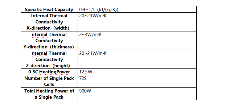
2.2Specification information of heat source devices:
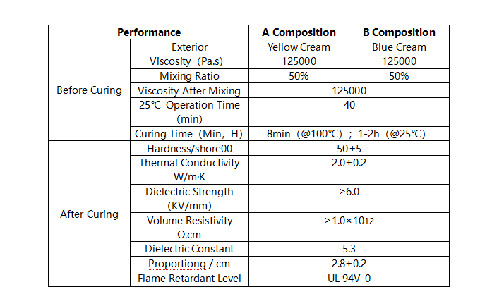
2.3 Thermal Conductive Silicone
3-Heat Dissipation Model
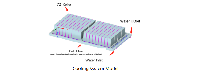
A battery pack that uses liquid cooling for heat dissipation, consisting of 72 280AH cells and a liquid cooling plate. The size of the liquid cooling plate is 1570mm in length, 960mm in width, and 42mm in height, with 24 internal flow channels. The heat dissipation model of the battery pack is shown in the following figure:
4-Simulation Results Under The Condition of Inlet Water of 8L/min
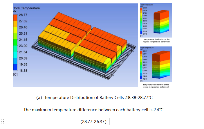
The temperature distribution of the battery cells is 18.38-28.77 ℃, with the temperature distribution range of the highest temperature cell being 21.46-26.37 ℃ and the temperature distribution range of the lowest temperature cell being 18.76-26.37 ℃. As shown in Figure (a):
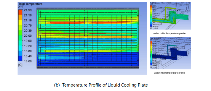
Temperature distribution of liquid cooled plate: 18.00-21.99℃,as shown in Figure (b):
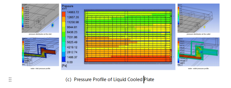
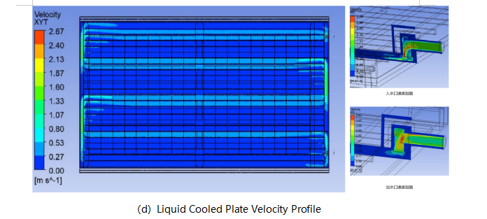
The flow resistance is about 17KPa, the pressure profile of the liquid cooling plate is shown in Figure (c), and the velocity profile of the liquid cooling plate is shown in Figure(d):
5-Conclusion
In this plan, the overall temperature ranges from 18.38 to 28.77 ℃, with a temperature difference of 2.4 ℃ between the highest and lowest battery cells. The overall temperature of the liquid cooled plate ranges from 18.00 to 21.99 ℃, the uniformity of temperature still needs to be optimized, multiple high-temperature areas have appeared.
Compare the pressure and velocity profile of the liquid cooling plate, the high-temperature area of the liquid cooling plate is mainly distributed in areas with lower pressure and velocity. Based on the layout of the battery cells, it can be seen that the width margin of the liquid cooling plate is relatively large. It is recommended to block the two outermost flow channels of the liquid cooling plate, or appropriately reduce the width of the liquid cooling plate to achieve better heat dissipation effect.