Communication and sharing promote growth
Joining Hands for Development!

The potential failure of the liquid-tightness of the energy storage liquid cooling pack involves multiple aspects, such as: leakage, corrosion and deposition, condensation water and other failure modes.
1- Fluid interconnection and composition
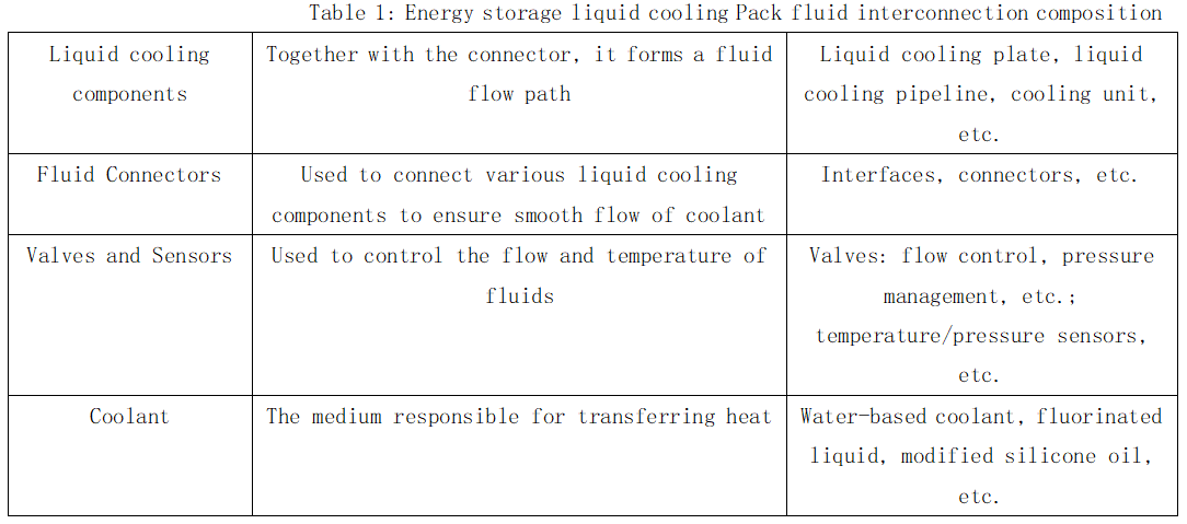
In the energy storage liquid cooling system, the fluid interconnection is responsible for transferring the coolant between the various components. Through effective fluid interconnection, the coolant is ensured to circulate efficiently in the system, thereby removing the excess heat generated during the battery charging and discharging process.

A well-sealed system can effectively prevent coolant leakage. Leakage will not only lead to coolant loss and require frequent replenishment, but also affect the heat dissipation performance and stability of the system. In energy storage, coolant leakage may also cause battery Short circuit, causing safety problems.
2-Liquid-tight design of fluid interconnection system
The liquid-tight design of the fluid interconnection system is the key link to ensure that the system maintains sealing and prevents fluid leakage under various operating conditions.

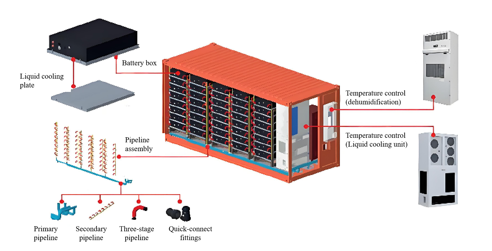
Figure 1: Typical deployment of energy storage liquid cooling system
(1) Analyze possible leakage sources and risk points in the system:
l The self-sealing property of the liquid cooling assembly. For example, in the integrated design of the liquid cooling channel system and the Pack box, the components are connected by welding. Welding quality defects, poor welding, pores, cracks, etc. may all lead to liquid seepage problems.
l The structural design is unreasonable. For example, the positioning holes or threaded holes of the liquid cooling box are too close to the flow channel, and the poorly welded parts can easily become channels for liquid seepage.
l Connection parts: The pipe connections, valves and joints of the liquid cooling system are common leakage points. If the connection structure is not designed properly or the manufacturing process is not sophisticated, there are tiny defects inside the joints, and the coolant may also leak from these defects.
l Leakage caused by improper installation, material aging or damage, etc.
(2) Sealing structure design:
l The liquid-cooled PACK uses a dry-wet separated cold plate cooling method. Under normal working conditions, the battery cells have no contact with the coolant, which can ensure the normal operation of the battery cells. One solution for the energy storage liquid cooler is to form it through an extrusion process, integrate the flow channel directly on the cold plate, and then use mechanical processing to open up the cooling circulation path. In this process, choosing the right welding process is an important step to ensure sealing. For details, please refer to "Design of welding process for lower box for energy storage".
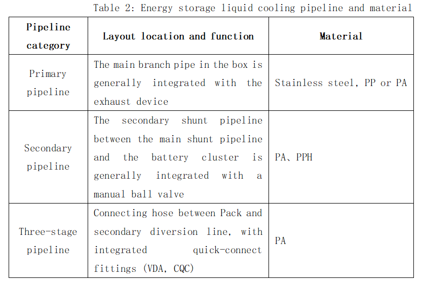
l Liquid cooling pipelines are mainly used for transitional soft (hard) pipe connections between liquid cooling sources and equipment, between equipment, and between equipment and pipelines. The main connection methods are:
Quick-connection: One of the connection methods for energy storage liquid cooling systems is to use VDA or CQC quick-connection.
Threaded connection: Both ends of the connection structure are slidably connected with pipes, and the threaded connection between the internal thread ring and the threaded sleeve increases the firmness of the connection.
Limiting pipe and nut connection: A connecting pipe is clamped at one end of the pipe, and limiting pipes are fixedly installed on both sides of the connecting pipe. Rubber washers and convex rings are fixedly installed inside the limiting pipes, and a limiting ring groove is opened on the surface of the connecting pipe head. A nut is rotatably connected to the top of the limiting tube and is rotatably connected to the limiting tube through threads.
Sealing ring connection: A sealing ring is adhered to the inner wall of the threaded sleeve by strong glue, and the inner wall of the sealing ring is movably connected to the outer surface of the pipe to prevent leakage during use.

(3) The PACK liquid cooling plate, cabin interface, cabin pipeline, etc. are all designed with long-term corrosion protection under common coolant, common temperature and flow rate conditions to ensure long-term operation without corrosion. Effect of operating conditions on liquid tightness:
l Temperature. Influence of high temperature: As the temperature increases, the viscosity of the liquid generally decreases, which may cause the sealing performance of the liquid to decrease, thereby affecting the liquid tightness. For example, certain sealing materials may deform or deteriorate at high temperatures, causing leakage. Influence of low temperature: In a low temperature environment, the liquid may become viscous, increasing the difficulty of flow, but it may also improve the performance of the sealing material, thereby enhancing liquid tightness to a certain extent.
l Pressure. High pressure environment: Under high pressure, the density and viscosity of the liquid may increase, thereby improving the sealing performance of the liquid. However, excessive pressure may also damage the sealing material and cause leakage. Low-pressure environment: Under low pressure, the sealing performance of the liquid may be relatively weak, especially if the sealing material itself is defective or aged, it is more likely to leak.
l Flow rate. High flow rate: When the liquid flows at high speed, it may produce a large impact force on the sealing surface, causing wear or deformation of the sealing material, thereby affecting the liquid tightness. Low flow rate: At low flow rate, the sealing performance of the liquid is relatively good, but this may also mask some potential sealing problems such as minor material defects.
3-Corrosion and deposition problems
l Effects of blocking on confidentiality:
Coolant, deposits or boiler growth may cause internal blockages, poor coolant flow and reduced cooling efficiency.
Fouling and scaling: Minerals in the coolant may form deposits on the inner wall of the pipe after long-term operation, which is called "scale". Fouling may also be formed due to solid particle precipitation, crystallization, corrosion or microbial activity. These dirt will clog pipes and cold plates, increase flow resistance and reduce heat transfer efficiency.
Foam problem: Foam may be generated in the liquid cooling system. The foam will adhere to the surface of the cold plate, resulting in a decrease in heat transfer effect, and may increase the resistance in system operation, cause cavitation corrosion to the pump, etc., and damage the equipment.
l The influence of eddy current on air tightness:
When a fluid flows in a pipe or gap, changes in velocity can cause eddies to form, especially when the fluid passes through narrow parts or obstacles, eddies are more likely to form. The viscosity and density of the fluid also affect the generation of vortices. Fluids with higher viscosity are more likely to form vortices, while fluids with higher density may weaken the formation of vortices.
Leakage paths: Eddy currents form vortices on contact surfaces, which may form tiny leakage paths in gaps or irregular surfaces, resulting in leakage of gas or liquid.
Surface wear: Eddy flow can cause wear of contact surfaces, especially in high-speed flow conditions. This wear can further reduce air tightness because the worn surfaces are more likely to form new leakage channels.
Thermal effects: Eddy current flow generates heat, which may cause deformation or thermal expansion of the contact surface material, thus affecting the airtightness, especially in systems with large temperature changes.
4-Condensation water problem
Under certain conditions, condensation may form in the liquid cooling lines, which may cause damage to the equipment or reduce efficiency. Insulation failure: If the insulation material of the pipe is damaged or aged, heat will be lost and the cooling effect will be affected. Especially in low temperature environments, insulation failure can cause frost or ice to form on the pipe surface. Frost cracking: In cold environments, if proper antifreeze measures are not taken, the coolant in the pipes may freeze and cause the pipes to rupture.
Solutions
l Sealing measures: Ensure that the inlet and outlet of the liquid cooling pipeline are completely blocked to prevent external humid air from entering the battery compartment.
l Dehumidification equipment: Install a dehumidification air conditioner or use the dehumidification function to maintain the humidity in the battery compartment within an appropriate range.
l Temperature control: By installing air conditioning or ventilation systems, the temperature and humidity of the environment where the energy storage cabinet is located can be controlled. For example, the temperature can be kept at 20-25 degrees Celsius and the relative humidity can be controlled at 40%-60%.
l Isolation measures: Simple isolation of empty battery racks to prevent moisture from entering the compartment containing the battery cluster.
We will regularly update you on technologies and information related to thermal design and lightweighting, sharing them for your reference. Thank you for your attention to Walmate.